Mating to a curved slotted hole in solid works
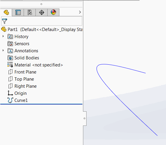
1.)Make a sketch of the centerline, part with the slot. 2.) Extrude a surface from this sketch 3.) Mate the axis of the bolt (or spigot) to the centerline surface with a coincident mate. It's a little roundabout, but it may help you skirt the learning curve for physical dynamics if time is an issue. Gravity is a harsh mistress. Slot Mate - Free Slot Casino. Welcome to join the most exciting free slot machine. Slot Mate will give you the best experience!
Mating to a curved slotted hole in solid works

Video on mating the curved slots across a curved path with cylindrical pins solidworks. SLOT MATE IN SOLIDWORKS 2016 - Duration: 4:39. CAD tutor SYED NADHEEM 3,328 views. To add a cam-follower mate: Click Mate (Assembly toolbar) or Insert Mate. In the PropertyManager, under Mechanical Mates, click Cam. Under Mate Selections, for Entities to Mate. Well Mate, no worries, you can get control of this rubbish quick fast and in a hurry with the SOLIDWORKS MATE CONTROLLER. The SOLIDWORKS MATE CONTROLLER allows us to easily manipulate Angle, Distance, LimitAngle, LimitDistance, Slot, and Width mates. First we'll activate the Mate Controller (Insert Mate Controller).

I am using both 2001 and 2001+.
I am trying to model a spigot mating with a 'curved' slotted hole(ie the parts rotate about another centre and are restained by the curved slot). The spigot needs to be able to move in the slotted hole but be restrained by the ends of the slot, so that i can confirm the design. The slotted hole is situated on some cable chain, that rotates through a certain angle (yet to be confirmed). I have tried several ways and found that it could be done for a couple of links if i mate the inside surface of the slot with the outside surface of the spigot (cam tangent mate), but when i do this for ~50 links i get an over defined error/fully defined error.
if there is way of getting around this, it would be bloody good, if you could give me an answer in detail as although i have a pretty good handle on the basics i have only spent 20+ hrs on solid works.
Cheers
Ryan
Imagine a slot and a pin:
.. _____________
<> _____________>

Video on mating the curved slots across a curved path with cylindrical pins solidworks. SLOT MATE IN SOLIDWORKS 2016 - Duration: 4:39. CAD tutor SYED NADHEEM 3,328 views. To add a cam-follower mate: Click Mate (Assembly toolbar) or Insert Mate. In the PropertyManager, under Mechanical Mates, click Cam. Under Mate Selections, for Entities to Mate. Well Mate, no worries, you can get control of this rubbish quick fast and in a hurry with the SOLIDWORKS MATE CONTROLLER. The SOLIDWORKS MATE CONTROLLER allows us to easily manipulate Angle, Distance, LimitAngle, LimitDistance, Slot, and Width mates. First we'll activate the Mate Controller (Insert Mate Controller).
I am using both 2001 and 2001+.
I am trying to model a spigot mating with a 'curved' slotted hole(ie the parts rotate about another centre and are restained by the curved slot). The spigot needs to be able to move in the slotted hole but be restrained by the ends of the slot, so that i can confirm the design. The slotted hole is situated on some cable chain, that rotates through a certain angle (yet to be confirmed). I have tried several ways and found that it could be done for a couple of links if i mate the inside surface of the slot with the outside surface of the spigot (cam tangent mate), but when i do this for ~50 links i get an over defined error/fully defined error.
if there is way of getting around this, it would be bloody good, if you could give me an answer in detail as although i have a pretty good handle on the basics i have only spent 20+ hrs on solid works.
Cheers
Ryan
Imagine a slot and a pin:
.. _____________
<> _____________>
Solidworks Sliding Mate
I am trying to use a limit mate to make the slot stop at the side of the pin but it is not working as intended. Before mating I selected the cylindrical face of each feature then specified limits. It does not stop at the pin but moves in both directions. Is this a limitation of the limit mate type or am I misunderstanding the functionality?
Curved Slot Solidworks
3 Answers
Ok to make it move and be limited in that one direction, you need to make a plane at the center of one ends slot diameter (green plane in picture) at the part document level. Then go back to the assembly and select that plane and click mate, select the parallel plane in the center of the pin, then click your limit dimension mate, the minimal distance will be set at zero, and the max will be the amount of travel (length of slot center to center.) Hope that helps. Petit casino zenith.
I would do this by using planes, unless you need the slotted part to rotate and slide. I've upload an assembly for reference. Pin/Slot Limit mate
Using Slot Mate Solidworks
Alright, so I created a plane at the center of the pin hole then mated it with the edge of the radius on the slot and it works really well. Now I can get back to the gears. Thanks so much!
